Introduction
The performance of a web guiding system depends on the positional accuracy of the guide mechanism, the accuracy of the sensor, the precision of the sensor, the dynamic response of the sensor (speed of measurement) and the dynamic performance of the actuator positioning the guide mechanism. The accuracy, precision and linearity of the sensor measurement was discussed in a previous white paper along with the discussion of sensing performance of the ARIS web position sensor in another white paper. In this white paper we discuss the dynamic response capability of the web guide mechanism.
“Frequency response” or the “bandwidth” of the guide mechanism characterizes the dynamic response of the guide mechanism. In general the higher the bandwidth, the faster the guide mechanism can respond to disturbances. Intermediate guides such as a steering guide or a displacement guide are typically powered by an electric motor through a coupling and actuation system. Other less common actuation systems in intermediate web guides include pneumatic and hydraulic cylinders.
The overall frequency response of the web guide mechanism is a function of the power available to the motor, the capability of the motor, the capability of the actuator, losses in the coupling mechanism, the mechanical friction/transmission losses and the overall inertia of the guide mechanism. In order to maximize the bandwidth or frequency response of the guide mechanism the overall electro-mechanism system should include:
- high performance motor, motor driver and power supply
- actuator with low transmission losses and backlash
- low friction transmission system and mechanical assembly
High Performance Guide Mechanism
The compact web guiding system is a type of displacement web guide equipped with a high performance linear hybrid stepper actuator. The linear hybrid stepper actuator is directly coupled to a low friction linear bearing system that supports the roller platform of the guide mechanism (see Fig. 1).
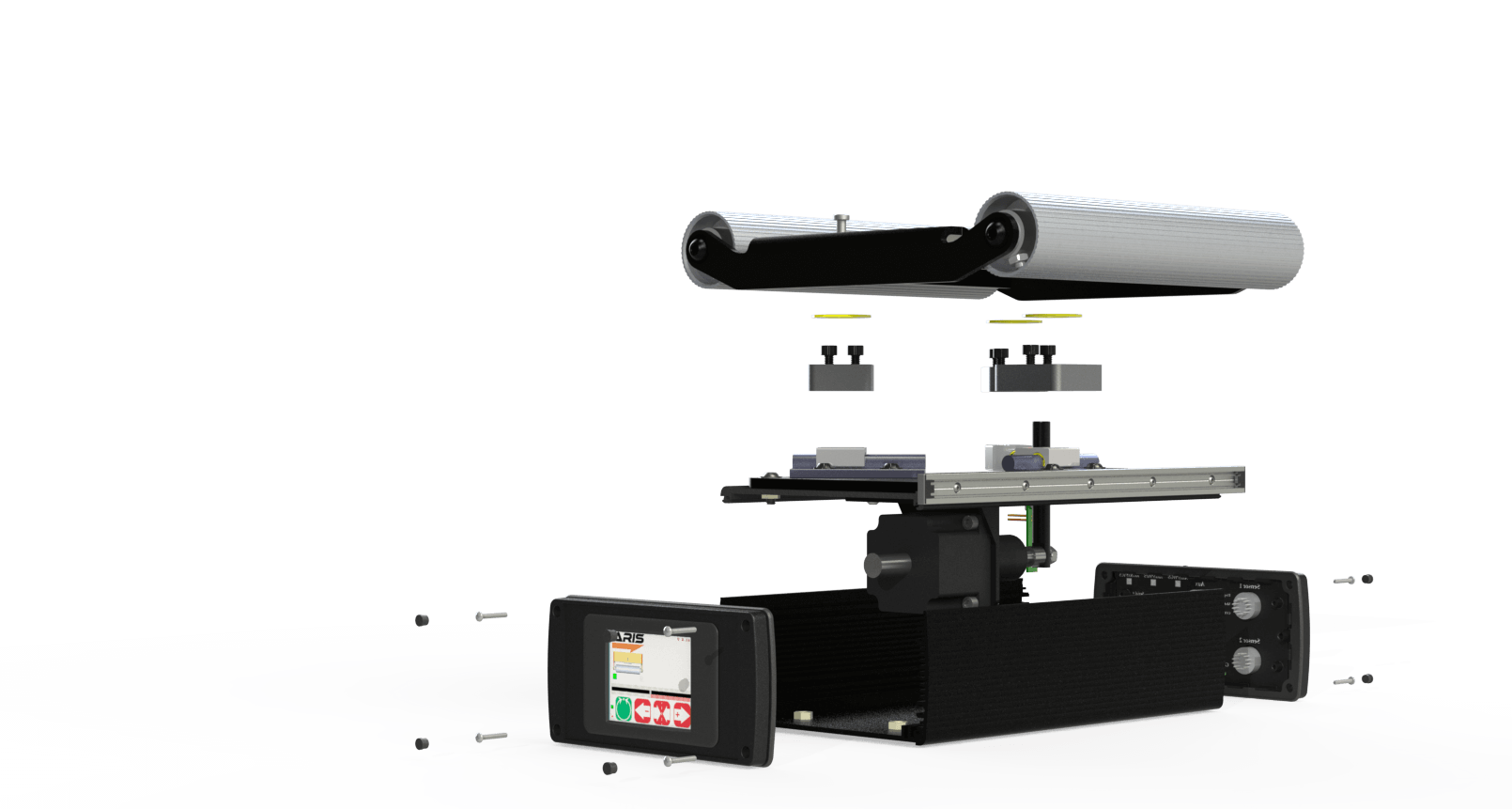
The linear hybrid actuator has a resolution of 0.0508 mm/step or 0.000198 mm/microstep. Based on the transmission ratio of the guide mechanism, each step corresponds to 0.0704 mm. The linear hybrid actuator is powered by a high performance constant current chopper drive which can generate in excess of 500,000 microsteps per second. Hence the overall maximum speed of the guide mechanism is about 130 mm/sec or 5.12 in/sec. The detailed specification of the guide mechanism is shown in table 1 below.
| Specification | Dimension/Value | Units |
|---|---|---|
| Roller Width | 254 | mm |
| Maximum Correction | 52.75 | mm |
| Displacement Resolution | 0.000275 | mm |
| Maximum Linear Speed | 130.00 | mm/sec |
| Maximum Linear Force | 250 | N |
| Time period for maximum correction | 0.425 | sec |
| Control frequency | 200 | Hz |
Frequency Response of the Guide Mechanism
One way to efficiently summarize the performance of the web guide mechanism is through its frequency response. The constant current chopper driver and the stepper motor are highly non-linear switching systems. Therefore a traditional frequency response based on a Bode diagram cannot be obtained. However, given all the parameters of the driver and the stepper motor, it is possible to analytically compute the maximum amplitude of travel for a sinusoidal reference input for a given frequency. Fig. 2 shows the theoretical frequency response for the high performance guide mechanism. The blue solid line shows the theoretical maximum possible correction for frequencies in the range of 1 to 10 Hz.
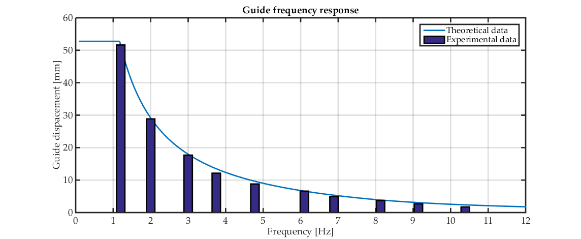
Set of experiments were performed at frequencies between 1 Hz and 10 Hz to compare the theoretical response with the actual response measured from the guide mechanism. The high performance stepper motor driver was used to command the motor to oscillate at a given frequency with the maximum amplitude. The actual movement of the guiding system were measured using a linear optical quadrature encoder with a resolution of 0.003175 mm/count. The encoder measurement was used to verify that the linear hybrid stepper actuator motor does not stall at high microstep pulse rates. The encoder measurement indeed verified the high precision performance of the system which closely matches the theoretical response without any stalling. Stalling is a common issue with low quality voltage based stepper drives. It is important to ensure that high performance constant current chopper driver is used to prevent stalling.
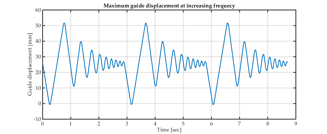
Fig. 3 shows the time domain data from the experiments. The ordinate shows the guide mechanism displacement in millimeters. The displacement is measured using the linear optical encoder. The abscissa is time in seconds. Note that at low frequencies the maximum travel is bounded by the stroke length of the linear hybrid actuator, while at higher frequencies it is limited by the maximum speed of the actuator. A video showing the frequency response of the guide is available here.
Conclusion
The performance data shows that as the frequency increases above 5 Hz the maximum possible correction drops below 10 mm. Additional performance increases are possible with custom actuators and motor drivers as discussed in another white paper. It has to be noted that guide mechanism inertia, the friction system and transmission compliance would become limiting factors for increasing bandwidth.
